
Tutorial Lengkap Cara Membuat Garis Putus Putus di AutoCAD
AutoCAD is a popular software used by many professionals in the field of design and drafting. One of the essential skills that you need to learn in AutoCAD is how to create dashed lines. Dashed lines are commonly used to represent hidden lines, construction lines, or any other lines that need to be visually distinguished from solid lines. In this tutorial, we will guide you through the process of creating dashed lines in AutoCAD.
To create dashed lines in AutoCAD, follow these steps:
Step 1: Open AutoCAD and Start a New Drawing
Launch AutoCAD and start a new drawing by clicking on “New” in the File menu or using the shortcut Ctrl + N. This will open a blank drawing window.
Step 2: Draw a Line
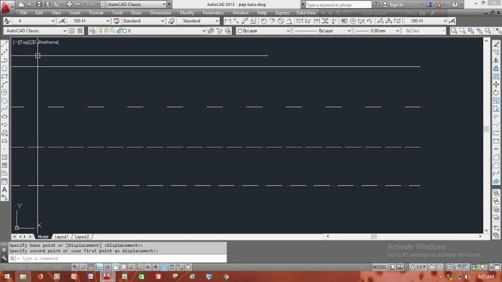
Next, use the Line command to draw a line by clicking on the “Line” button in the Draw toolbar or using the shortcut L. Specify the starting point of the line by clicking on a point in the drawing area, then specify the endpoint of the line by clicking on another point. This will create a solid line.
Step 3: Change the Linetype
To create a dashed line, we need to change the linetype. In AutoCAD, linetypes define the pattern and appearance of lines. By default, AutoCAD uses the “Continuous” linetype, which creates solid lines. To change the linetype, follow these steps:
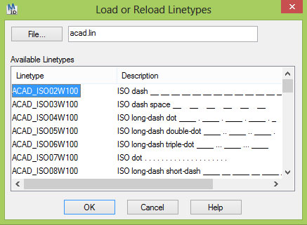
1. Type “Linetype” in the command line and press Enter. This will open the Linetype Manager dialog box.
2. In the Linetype Manager dialog box, click on the “Load” button. This will open a file browser window.
3. Browse to the AutoCAD installation directory (usually located in C:\Program Files\Autodesk\AutoCAD version) and open the “acad.lin” file. This file contains a collection of predefined linetypes.
4. In the Linetype Manager dialog box, select the desired linetype from the list. AutoCAD provides various linetypes, including dashed, dotted, and dash-dot patterns.
5. Click on the “Set Current” button to set the selected linetype as the current linetype.
6. Close the Linetype Manager dialog box by clicking on the “OK” button.
Step 4: Apply the Linetype to the Line
Now that we have changed the linetype, we can apply it to our line. To apply the linetype, follow these steps:
1. Type “Properties” in the command line and press Enter. This will open the Properties palette.
2. In the Properties palette, select the line that you want to change the linetype for.
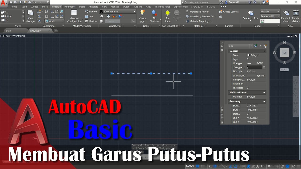
3. In the Properties palette, scroll down to the “Linetype” section and click on the linetype drop-down list.
4. Select the desired linetype from the list. The selected linetype will be applied to the line.
5. Close the Properties palette.
Step 5: Modify the Linetype Scale (Optional)
By default, AutoCAD sets the linetype scale to 1.0, which means that the linetype will be displayed at its default size. However, you can modify the linetype scale to adjust the size of the dashed lines. To modify the linetype scale, follow these steps:
1. Type “Ltscale” in the command line and press Enter. This will open the Linetype Scale dialog box.
2. In the Linetype Scale dialog box, enter a scale factor for the linetype. The scale factor determines the size of the dashes and gaps in the linetype. For example, entering a scale factor of 2.0 will double the size of the dashes and gaps, while entering a scale factor of 0.5 will halve the size of the dashes and gaps.
3. Click on the “OK” button to apply the linetype scale.
4. Close the Linetype Scale dialog box.
Step 6: Create More Dashed Lines (Optional)
Now that you have learned how to create dashed lines in AutoCAD, you can practice by creating more dashed lines. Experiment with different linetypes, linetype scales, and line lengths to achieve the desired effects. Remember to always select the line and apply the desired linetype using the Properties palette.
Creating dashed lines in AutoCAD is a fundamental skill that every AutoCAD user should learn. Whether you are working on architectural drawings, mechanical designs, or any other type of technical drawing, knowing how to create dashed lines will greatly enhance your productivity and the visual clarity of your drawings. Practice the steps outlined in this tutorial, and soon you will be able to create professional-looking dashed lines in AutoCAD with ease.
If you are looking for Cara Membuat Garis Putus Putus di Autocad dengan Benar Updated 2023 you’ve came to the right web. We have 3 Pics about Cara Membuat Garis Putus Putus di Autocad dengan Benar Updated 2023 like Cara Membuat Garis Putus Putus di Autocad dengan Benar Updated 2023, Cara Membuat Garis Putus-Putus di AutoCAD dengan Mudah and also Cara Membuat Garis Putus-Putus di AutoCAD dengan Mudah. Here it is:
Cara Membuat Garis Putus Putus Di Autocad Dengan Benar Updated 2023
lulusantekno.com
Tutorial Lengkap Cara Membuat Garis Putus Putus Di AutoCAD
www.asifah.com
putus garis autocad jenis kemudian muncul linetype sekarang kotak
Cara Membuat Garis Putus-Putus Di AutoCAD Dengan Mudah
mepis-deb.org
Tutorial lengkap cara membuat garis putus putus di autocad. Cara membuat garis putus putus di autocad dengan benar updated 2023. Cara membuat garis putus-putus di autocad dengan mudah